6.Cisco ASA Remote Access VPN
In this lesson we’ll take a look how to configure remote access IPsec VPN using the Cisco VPN client. This allows remote users to connect to the ASA and access the remote network through an IPsec encrypted tunnel.
The remote user requires the Cisco VPN client software on his/her computer, once the connection is established the user will receive a private IP address from the ASA and has access to the network.
The Cisco VPN client is end-of-life and has been replaced by the Cisco Anyconnect Secure Mobility Client. It’s not supported any more but still widely in use nowadays.
This is the topology that we will use for this example:

The ASA has two interfaces: inside and outside. Imagine the outside interface is connected to the Internet where a remote user wants to connect to the ASA. On the inside we find R1, I will only use this router so the remote user has something to connect to on the inside network. Let’s look at the configuration!
1.Configuration
1.1.VPN Pool
First we will configure a pool with IP addresses that we will assign to remote VPN users:
ASA1(config)# ip local pool VPN_POOL 192.168.10.100-192.168.10.200I will use IP address 192.168.10.100 – 192.168.10.200 for our VPN users. We need to tell the ASA that we will use this local pool for remote VPN users:
ASA1(config)# vpn-addr-assign localThis is done with the vpn-addr-assign command.
1.2.NAT Exemption
If you have NAT enabled on the ASA then we need to make sure that traffic between 192.168.1.0 /24 (the local network) and 192.168.10.0 /24 (our remote VPN users) doesn’t get translated. To accomplish this we will configure NAT excemption. The example below is for ASA version 8.3 or higher:
ASA1(config)# object network LAN
ASA1(config-network-object)# subnet 192.168.1.0 255.255.255.0

ASA1(config)# object network VPN_POOL
ASA1(config-network-object)# subnet 192.168.10.0 255.255.255.0

ASA1(config)# nat (INSIDE,OUTSIDE) source static LAN LAN destination static VPN_POOL VPN_POOL
We create two network objects, one for our local network and another one for the remote VPN users. The NAT rule tells the ASA not to translate traffic between the two networks.
1.3.Group Policy
When the remote user has established the VPN, he or she will be unable to access anything on the Internet…only the remote network is reachable. For security reasons this is a good practice as it forces you to send all traffic through the ASA. If you don’t want this then you can enable split tunneling. With split tunneling enabled, we will use the VPN only for access to the remote network. Here’s how to enable it:
ASA1(config)# access-list SPLIT_TUNNEL standard permit 192.168.1.0 255.255.255.0Now we can create a group policy. This allows you to assign different remote users to different groups with different attributes. You might want to have a group policy for “network engineers” and another one for “regular users” each with different DNS servers, timeout settings, etc. Here’s an example:
ASA1(config)# group-policy VPN_POLICY internal
ASA1(config)# group-policy VPN_POLICY attributes
ASA1(config-group-policy)# dns-server value 8.8.8.8
ASA1(config-group-policy)# vpn-idle-timeout 15
ASA1(config-group-policy)# split-tunnel-policy tunnelspecified
ASA1(config-group-policy)# split-tunnel-network-list value SPLIT_TUNNEL
The group policy is called VPN_POLICY and it’s an internal group policy which means it is created locally on the ASA. You can also specify an external group policy on a RADIUS server. I added some attributes, for example a DNS server and an idle timeout (15 minutes). Split tunneling is optional but I added it to show you how to use it, it refers to the access-list we created earlier.
If you want to configure an access-list so the remote VPN users can only reach certain networks, IP addresses or ports then you can apply this under the group policy.
Let’s continue and create a user for remote access:
1.4.Username
ASA1(config)# username VPN_USER password MY_PASSWORDWe configured a group policy and user but we haven’t configured any IPsec settings yet. Let’s configure phase 1…
1.5.IPsec Phase 1
ASA1(config)# crypto ikev1 policy 10
ASA1(config-ikev1-policy)# encryption aes
ASA1(config-ikev1-policy)# hash sha
ASA1(config-ikev1-policy)# authentication pre-share
ASA1(config-ikev1-policy)# group 2
ASA1(config-ikev1-policy)# lifetime 86400
This is just a basic example. We will use AES for encryption, SHA for integrity, a pre-shared key and Diffie-Hellman group 2 for key exchange. The lifetime before we have to do a renegotiation is 86400 seconds. Let’s enable this IKEv1 policy on the outside interface:
ASA1(config)# crypto ikev1 enable OUTSIDE
ASA1(config)# crypto isakmp identity address
And we can continue with phase 2:
1.6.IPsec Phase 2
ASA1(config)# crypto ipsec ikev1 transform-set MY_TRANSFORM_SET esp-aes esp-sha-hmacWe will configure a transform set called “MY_TRANSFORM_SET” and we use ESP with AES/SHA. The next step is to configure a crypto map, this has to be a dynamic crypto map since the remote VPN users probably are behind dynamic IP addresses and we don’t know which ones:
ASA1(config)# crypto dynamic-map MY_DYNA_MAP 10 set ikev1 transform-set MY_TRANSFORM_SETThe dynamic crypto map is called “MY_DYNA_MAP” and it refers to the transform set. Even though we have a dynamic crypto map, we still have to attach this to a static crypto map like this:
ASA1(config)# crypto map MY_CRYPTO_MAP 10 ipsec-isakmp dynamic MY_DYNA_MAPAnd attach it to the outside interface:
ASA1(config)# crypto map MY_CRYPTO_MAP interface OUTSIDE1.7.Tunnel Group
The last step is to create a tunnel group. This binds the group policy and pool together and it’s where we configure a pre-shared key for the group policy:
ASA1(config)# tunnel-group MY_TUNNEL type remote-access
ASA1(config)# tunnel-group MY_TUNNEL general-attributes
ASA1(config-tunnel-general)# address-pool VPN_POOL
ASA1(config-tunnel-general)# default-group-policy VPN_POLICY
The tunnel group is called “MY_TUNNEL” and we add the pool and group policy. Now we can configure its attributes:
ASA1(config)# tunnel-group MY_TUNNEL ipsec-attributes
ASA1(config-tunnel-ipsec)# ikev1 pre-shared-key MY_SHARED_KEY
We’ll set the pre-shared key to “MY_SHARED_KEY”.
That’s all we have to do on the ASA, let’s look at the client now…
2.Verification
After installing the VPN client and starting it, you will see the following screen:

Click on New and you will see the following screen:
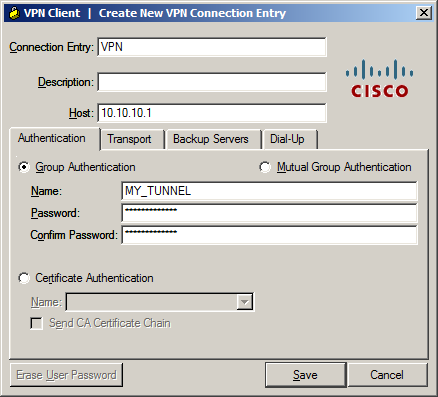
There are a couple of fields we have to enter here:
- Connection Entry and Description: Fill in whatever you like, these are only used as a general description of the connection.
- Host: This is the outside IP address of the ASA.
- Name: Enter the tunnel group name here, in our example “MY_TUNNEL”.
- Password: This is the pre-shared key under the tunnel group, not the user password! In our example this is “MY_SHARED_KEY”.
Click Save to save your settings to get back to the main screen:
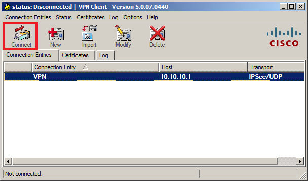
Hit the Connect button and you should get a pop-up that requests the user credentials:

Now you can enter the username and password that we created. Click on OK and you should get connected and see this:

In the bottom of the VPN client you will see that it is connected…excellent!
We are connected but it’s good practice to check a couple of things, first let’s see what IP address we received:
C:UsersVPN-PC>ipconfig /all

Windows IP Configuration

   Host Name . . . . . . . . . . . . : VPN-PC
   Primary Dns Suffix  . . . . . . . :
   Node Type . . . . . . . . . . . . : Hybrid
   IP Routing Enabled. . . . . . . . : No
   WINS Proxy Enabled. . . . . . . . : No

Ethernet adapter Local Area Connection 2:

   Connection-specific DNS Suffix  . :
   Description . . . . . . . . . . . : Cisco Systems VPN Adapter for 64-bit Windows
   Physical Address. . . . . . . . . : 00-05-9A-3C-78-00
   DHCP Enabled. . . . . . . . . . . : No
   Autoconfiguration Enabled . . . . : Yes
   Link-local IPv6 Address . . . . . : fe80::2815:c8ae:486:fade%20(Preferred)
   IPv4 Address. . . . . . . . . . . : 192.168.10.100(Preferred)
   Subnet Mask . . . . . . . . . . . : 255.255.255.0
   Default Gateway . . . . . . . . . :
   DHCPv6 IAID . . . . . . . . . . . : 419431834
   DHCPv6 Client DUID. . . . . . . . : 00-01-00-01-17-FF-B9-9F-00-0C-29-E7-0F-2E
   DNS Servers . . . . . . . . . . . : 8.8.8.8
   NetBIOS over Tcpip. . . . . . . . : Enabled
You can see the VPN client created an additional interface and it has received an IP address from the VPN pool. So far so good, let’s see if we have connectivity…I’ll send a ping to R1:
C:UsersVPN-PC>ping 192.168.1.1

Pinging 192.168.1.1 with 32 bytes of data:
Reply from 192.168.1.1: bytes=32 time=2ms TTL=255
Reply from 192.168.1.1: bytes=32 time=1ms TTL=255
Reply from 192.168.1.1: bytes=32 time=1ms TTL=255
Reply from 192.168.1.1: bytes=32 time=10ms TTL=255

Ping statistics for 192.168.1.1:
    Packets: Sent = 4, Received = 4, Lost = 0 (0% loss),
Approximate round trip times in milli-seconds:
    Minimum = 1ms, Maximum = 10ms, Average = 3ms
Our remote VPN user is able to reach R1, let’s see what the ASA thinks of this:
ASA1# show crypto ipsec sa
interface: OUTSIDE
    Crypto map tag: MY_DYNA_MAP, seq num: 10, local addr: 10.10.10.1

      local ident (addr/mask/prot/port): (0.0.0.0/0.0.0.0/0/0)
      remote ident (addr/mask/prot/port): (192.168.10.100/255.255.255.255/0/0)
      current_peer: 10.10.10.2, username: VPN_USER
      dynamic allocated peer ip: 192.168.10.100
      dynamic allocated peer ip(ipv6): 0.0.0.0

      #pkts encaps: 4, #pkts encrypt: 4, #pkts digest: 4
      #pkts decaps: 4, #pkts decrypt: 4, #pkts verify: 4
      #pkts compressed: 0, #pkts decompressed: 0
      #pkts not compressed: 4, #pkts comp failed: 0, #pkts decomp failed: 0
      #pre-frag successes: 0, #pre-frag failures: 0, #fragments created: 0
      #PMTUs sent: 0, #PMTUs rcvd: 0, #decapsulated frgs needing reassembly: 0
      #TFC rcvd: 0, #TFC sent: 0
      #Valid ICMP Errors rcvd: 0, #Invalid ICMP Errors rcvd: 0
      #send errors: 0, #recv errors: 0

      local crypto endpt.: 10.10.10.1/0, remote crypto endpt.: 10.10.10.2/0
      path mtu 1500, ipsec overhead 74(44), media mtu 1500
      PMTU time remaining (sec): 0, DF policy: copy-df
      ICMP error validation: disabled, TFC packets: disabled
      current outbound spi: D7E67C68
      current inbound spi : CEB125F9

    inbound esp sas:
      spi: 0xCEB125F9 (3467716089)
         transform: esp-aes esp-sha-hmac no compression
         in use settings ={RA, Tunnel, IKEv1, }
         slot: 0, conn_id: 4096, crypto-map: MY_DYNA_MAP
         sa timing: remaining key lifetime (sec): 28558
         IV size: 16 bytes
         replay detection support: Y
         Anti replay bitmap:
          0x00000000 0x0000001F
    outbound esp sas:
      spi: 0xD7E67C68 (3622206568)
         transform: esp-aes esp-sha-hmac no compression
         in use settings ={RA, Tunnel, IKEv1, }
         slot: 0, conn_id: 4096, crypto-map: MY_DYNA_MAP
         sa timing: remaining key lifetime (sec): 28558
         IV size: 16 bytes
         replay detection support: Y
         Anti replay bitmap:
          0x00000000 0x00000001
The ASA tells us that user “VPN_USER” is connected and you can see the number of encrypted and decrypted packets. Everything is working as it should!
- Configurations
- ASA
- R1
hostname ciscoasa
!
ip local pool VPN_POOL 192.168.10.100-192.168.10.200
!
interface FastEthernet0/0
 nameif INSIDE
 security-level 100
 ip address 192.168.1.254 255.255.255.0
!
interface FastEthernet0/1
 nameif OUTSIDE
 security-level 0
 ip address dhcp setroute
!
object network LAN
 subnet 192.168.1.0 255.255.255.0
object network VPN_POOL
 subnet 192.168.10.0 255.255.255.0
access-list SPLIT_TUNNEL standard permit 192.168.1.0 255.255.255.0
!
nat (INSIDE,OUTSIDE) source static LAN LAN destination static VPN_POOL VPN_POOL
!
crypto ipsec ikev1 transform-set MY_TRANSFORM_SET esp-aes esp-sha-hmac
crypto ipsec security-association pmtu-aging infinite
crypto dynamic-map MY_DYNA_MAP 10 set ikev1 transform-set MY_TRANSFORM_SET
crypto map MY_CRYPTO_MAP 10 ipsec-isakmp dynamic MY_DYNA_MAP
crypto map MY_CRYPTO_MAP interface OUTSIDE
!
crypto isakmp identity address
crypto ikev1 enable OUTSIDE
crypto ikev1 policy 10
 authentication pre-share
 encryption aes
 hash sha
 group 2
 lifetime 86400
crypto ikev1 policy 65535
 authentication pre-share
 encryption 3des
 hash sha
 group 2
 lifetime 86400
!
group-policy VPN_POLICY internal
group-policy VPN_POLICY attributes
 dns-server value 8.8.8.8
 vpn-idle-timeout 15
 split-tunnel-policy tunnelspecified
 split-tunnel-network-list value SPLIT_TUNNEL
dynamic-access-policy-record DfltAccessPolicy
username VPN_USER password E5PbZWWQ.j3bJJHz encrypted
tunnel-group MY_TUNNEL type remote-access
tunnel-group MY_TUNNEL general-attributes
 address-pool VPN_POOL
 default-group-policy VPN_POLICY
tunnel-group MY_TUNNEL ipsec-attributes
 ikev1 pre-shared-key *****
!
class-map inspection_default
 match default-inspection-traffic
!
policy-map type inspect dns preset_dns_map
 parameters
  message-length maximum client auto
  message-length maximum 512
policy-map global_policy
 class inspection_default
  inspect ip-options
  inspect netbios
  inspect rtsp
  inspect sunrpc
  inspect tftp
  inspect xdmcp
  inspect dns preset_dns_map
  inspect ftp
  inspect h323 h225
  inspect h323 ras
  inspect rsh
  inspect esmtp
  inspect sqlnet
  inspect sip
  inspect skinny
policy-map type inspect dns migrated_dns_map_1
 parameters
  message-length maximum client auto
  message-length maximum 512
!
service-policy global_policy global
!
: end
hostname R1
!
interface GigabitEthernet0/1
ip address 192.168.1.1 255.255.255.0
duplex auto
speed auto
media-type rj45
!
ip route 0.0.0.0 0.0.0.0 192.168.1.254
!
endI hope this lesson has been useful to understand remote access VPN with the legacy VPN client. If you have any questions, feel free to leave a comment!

Comments
Post a Comment